555 Timer Astable Multivibrator Circuit Diagram

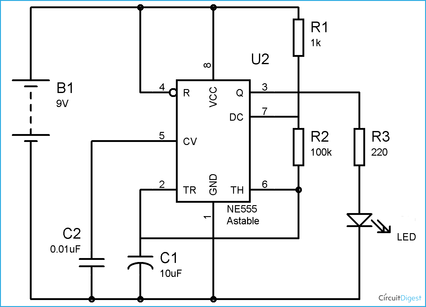
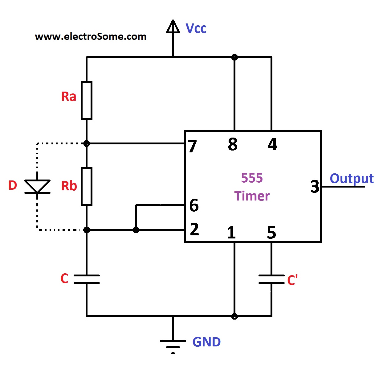
555 Timer Astable Multivibrator Circuit Diagram The schematic of the ic 555 as an astable multivibrator along with the three external components is shown below. ic 555 astable multivibrator circuit diagram: the pins 2 and 6 are connected and hence there is no need for an external trigger pulse. it will self trigger and act as a free running multivibrator (oscillator). In this 555 astable multivibrator circuit, led will switch on and off automatically with a particular duration. on time, off time, frequency etc can be calculated using above formulas. above figure shows the 555 timer astable multivibrator circuit diagram. you can find a lot of circuits and applications using astable mode in 555 timer circuits.

Astable Multivibrator Using 555 Timer 555 oscillator tutorial. the 555 ic can be used to create a free running astable oscillator to continuously produce square wave pulses. the 555 timer ic can be connected either in its monostable mode thereby producing a precision timer of a fixed time duration, or in its bistable mode to produce a flip flop type switching action. 555 timer astable multivibrator circuit diagram. an astable multivibrator can be designed by adding two resistors (ra and rb in circuit diagram) and a capacitor (c in circuit diagram) to the 555 timer ic. these two resistors and the capacitor (values) are selected appropriately so as to obtain the desired ‘on’ and ‘off’ timings at the. 555 circuits part 1 – the fastest 555 oscillator. by varying the value of either r or c the 555 astable multivibrator circuit can be made to oscillate at any desired output frequency. but what is the maximum frequency of oscillations we can produce from a single 555 timer chip. to get the 555 to operate at its highest frequency in this 555. It has a built in automatic triggering to switch between the states. to make our 555 timer act as an astable multivibrator, we just need to connect two external resistors and a capacitor as shown in the below schematic. we don't need an external switch in this mode because the switching is automated. figure 1: schematic of 555 timer as an.

Astable Multivibrator Using Ic 555 Circuit 555 circuits part 1 – the fastest 555 oscillator. by varying the value of either r or c the 555 astable multivibrator circuit can be made to oscillate at any desired output frequency. but what is the maximum frequency of oscillations we can produce from a single 555 timer chip. to get the 555 to operate at its highest frequency in this 555. It has a built in automatic triggering to switch between the states. to make our 555 timer act as an astable multivibrator, we just need to connect two external resistors and a capacitor as shown in the below schematic. we don't need an external switch in this mode because the switching is automated. figure 1: schematic of 555 timer as an. The following graph applies to the astable circuit: using the graph: suppose r1 = 1k, r2 = 10k and c = 0.1u (100n). using the formula on the graph, the total resistance = 1 10 10 = 21k. the scales on the graph are logarithmic so that 21k is approximately near the "1" on the 10k. draw a line parallel to the lines on the graph and where it. The 555 timer, designed by hans camenzind in 1971, can be found in many electronic devices starting from toys and kitchen appliances to even a spacecraft. it is a highly stable integrated circuit that can produce accurate time delays and oscillations. the 555 timer has three operating modes, bistable, monostable and astable mode.

Comments are closed.