2 Wire Temp Sensor Wiring Diagram

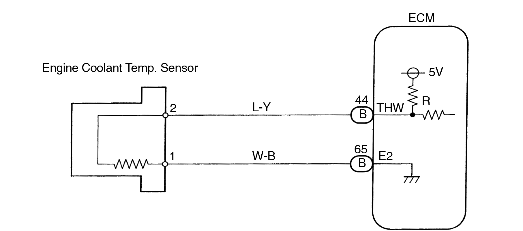
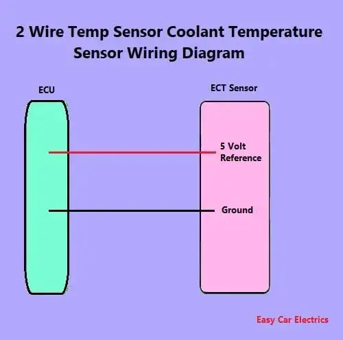
2 Wire Temp Sensor Coolant Temperature Sensor Wiring Di 3 wire coolant temperature sensor wiring diagram. the two wires, a “5 volt reference”, and a “ground wire” go to the ecu, and the third wire “earth 1 wire for temp gauge” goes to the cluster mounted temperature gauge by providing an earth link to the temperature gauge. in three wire coolant temp sensors, the ecu does not control the. A 2 wire temperature sensor, also known as a thermocouple or rtd (resistance temperature detector), is commonly used in industrial applications for measuring and monitoring temperature. wiring a 2 wire temp sensor requires connecting the two wires of the sensor to the appropriate terminals or pins on the temperature controller or monitoring device.

2 Wire Temp Sensor Wiring Diagram вђ A Comprehensive Guide вђ Moo Wiring Two wire temp sensors work based on the principle that the resistance of the sensor changes with temperature. as the temperature increases, the resistance of the sensor increases. by measuring this change in resistance, the temperature can be accurately determined. these sensors are commonly used in various industries such as hvac, automotive. To wire a 2 wire temperature sensor in an ls engine, you will need to identify the correct sensor and understand the wiring diagram of your specific ls engine model. the two wires of the sensor are typically color coded, with one wire being the signal wire and the other wire acting as the ground or reference wire. Two wire sensor working principle and animation. by editorial staff. sensors can also be broken down by their wiring configurations. the most common are 2 wire and 3 wire. two wire devices are designed to wire in series with the load. in a 3 wire configuration, two of the three leads supply power while the third switches the load. This effect can be minimized by using a three wire bridge configuration. in a 4 wire rtd configuration, two wires link the sensing element to the monitoring device on both sides of the sensing element. one set of wires delivers the current used for measurement, and the other set measures the voltage drop over the resistor.

1 2 3 Wire Coolant Temperature Sensor Wiring Diagram Two wire sensor working principle and animation. by editorial staff. sensors can also be broken down by their wiring configurations. the most common are 2 wire and 3 wire. two wire devices are designed to wire in series with the load. in a 3 wire configuration, two of the three leads supply power while the third switches the load. This effect can be minimized by using a three wire bridge configuration. in a 4 wire rtd configuration, two wires link the sensing element to the monitoring device on both sides of the sensing element. one set of wires delivers the current used for measurement, and the other set measures the voltage drop over the resistor. A 2 wire pt100 is a type of temperature sensor that uses a platinum resistance element to measure temperature. it is called a “2 wire” sensor because it only requires two wires for its operation. the pt100 sensor is designed to have a resistance of exactly 100 ohms at 0 degrees celsius. as the temperature changes, the resistance of the. Rtds are available in a wide range of styles, configurations and terminations and are available as either a 2 wire, 3 wire or 4 wire device. each wiring configuration has its own characteristics and advantages and they are usually colour coded as below: 2 wire rtd pt100 sensor = 1 x red lead wire and 1 white lead wire.

Comments are closed.